


Energy IQ / Build IQ / Comfort IQ
Air sealing: common leaks and practical repairs
Find common air-leakage paths around pipes, wiring, trim, doors and attic hatches, and match the repair to the joint.
Our articles are a starting point, not a professional assessment of your home.
DraftA work in progress, prepared by the HouseIQ.pro team.Editorial and professional review are not yet complete.
Choose a repair below
Use these drawings to locate the joint, choose the right seal and check the finished repair. They show typical details, not every wall assembly. The blower-door guide covers testing, pressure and ACH50.
Keep ventilation, drainage and combustion-air openings clear. Investigate dampness and damaged materials before sealing. Choose compatible products and follow their instructions.

Many distributed leakage paths can be represented by a single equivalent opening calculated from an air-leakage test at a stated reference pressure. This is an airflow comparison, not a literal sum of visible crack areas. The basketball provides a familiar scale only; actual results vary by home. Equivalent and effective leakage area use different definitions and reference pressures. Do not seal intentional ventilation or drainage openings.
Pipe penetrations and the joist-header area
- Find the gap where the cool pipe crosses the air barrier.
- Clean the joint; add suitable backing if the gap needs it.
- Apply a compatible continuous seal; check all the way around.
The joist-header or rim-joist area sits around the floor perimeter above the foundation. Include its joints and service penetrations in the assessment. At ordinary cool pipes, seal the gap between the pipe and air barrier with compatible material; larger gaps need suitable backing. Insulation alone does not seal that connection. Do not apply this detail to flues, hot pipes or required fire separations.
Sources: [13]
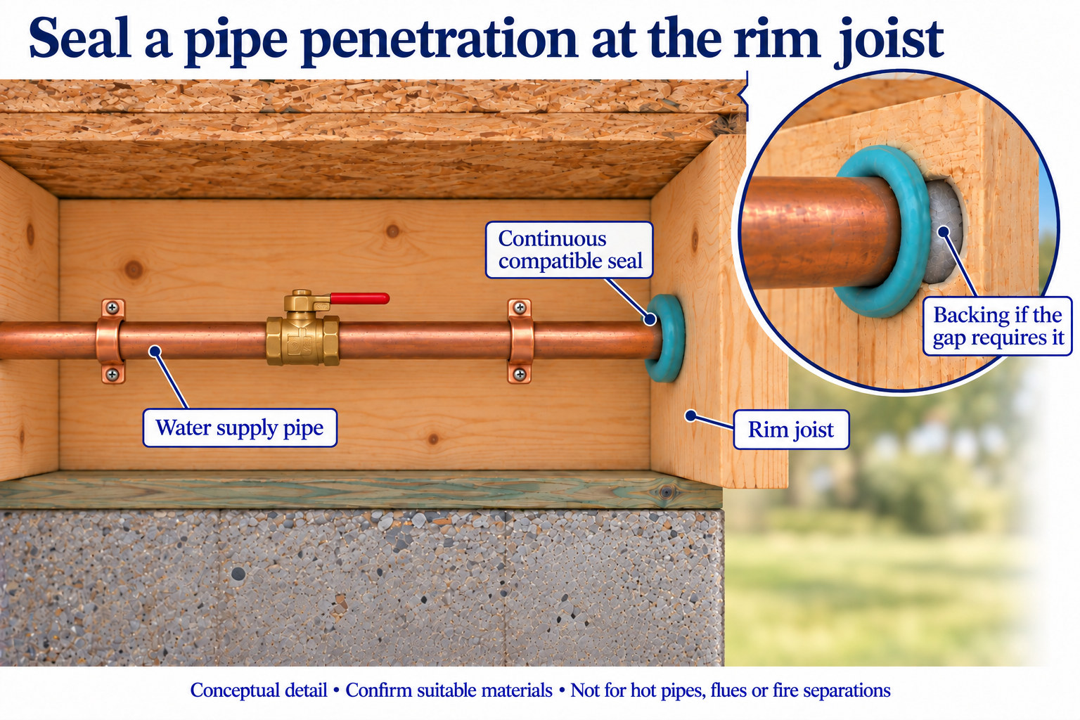
A straight copper water-supply line runs alongside a floor joist and passes through the rim joist above the sill plate and foundation. An inline shutoff provides plumbing context; the seal belongs only at the pipe-to-air-barrier joint. The inset shows suitable backing behind the compatible seal where the gap requires it. Confirm the service, materials and assembly before sealing; this is not a drilling, plumbing, freeze-protection or firestopping specification. Not for hot pipes, flues or fire separations.
Wires, top plates and hidden service routes
- Locate the cable opening at the air-control boundary.
- Use a sealant compatible with the cable jacket and assembly.
- Check the seal; keep junction boxes accessible.
A cable passing through a wall top plate can leave a route into the attic. An open chase can connect several storeys. These openings deserve attention when accessible during assessment or renovation, even if the draft is first noticed elsewhere. Sealing belongs at the air-control boundary; use materials compatible with the wiring and assembly. Preserve required fireblocking and firestopping. Do not bury junction boxes or make them inaccessible.
Sources: [14]
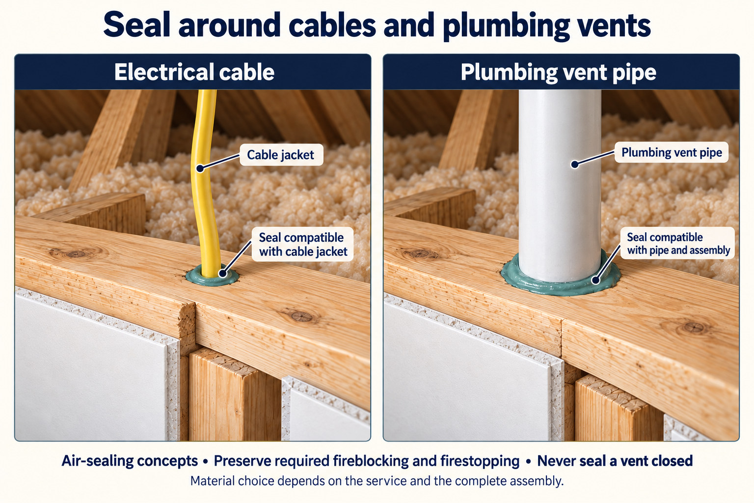
Two separate attic-side examples distinguish the intact jacket of an electrical cable from a larger plumbing vent pipe. Seal around the opening using materials compatible with the service and complete assembly; never seal a vent closed. Preserve required fireblocking and firestopping, keep junction boxes accessible, and use qualified access. These are air-sealing concepts, not drilling or firestopping specifications.
Electrical outlets and switch-plate gaskets
- Choose a purpose-made gasket certified or listed for use behind electrical cover plates, with a CSA, UL/cUL, ETL/cETL or equivalent mark accepted by the local electrical authority.
- Turn off the circuit and verify that it is de-energized.
- Remove only the cover plate; fit the correct purpose-made gasket.
- Refit the plate as directed; check that the gasket seats evenly.
Check the product or packaging for the appropriate certification mark and confirm that its approval covers this electrical application. A “fire-retardant” claim alone is not certification. Purpose-made gaskets fit behind cover plates to reduce leakage; they do not necessarily close hidden routes around the box. Follow the product instructions, turn off the circuit and verify it is de-energized before removing a plate. Do not put ordinary foam or caulk inside electrical boxes. Have an electrician assess damaged devices, wiring or deeper sealing work.
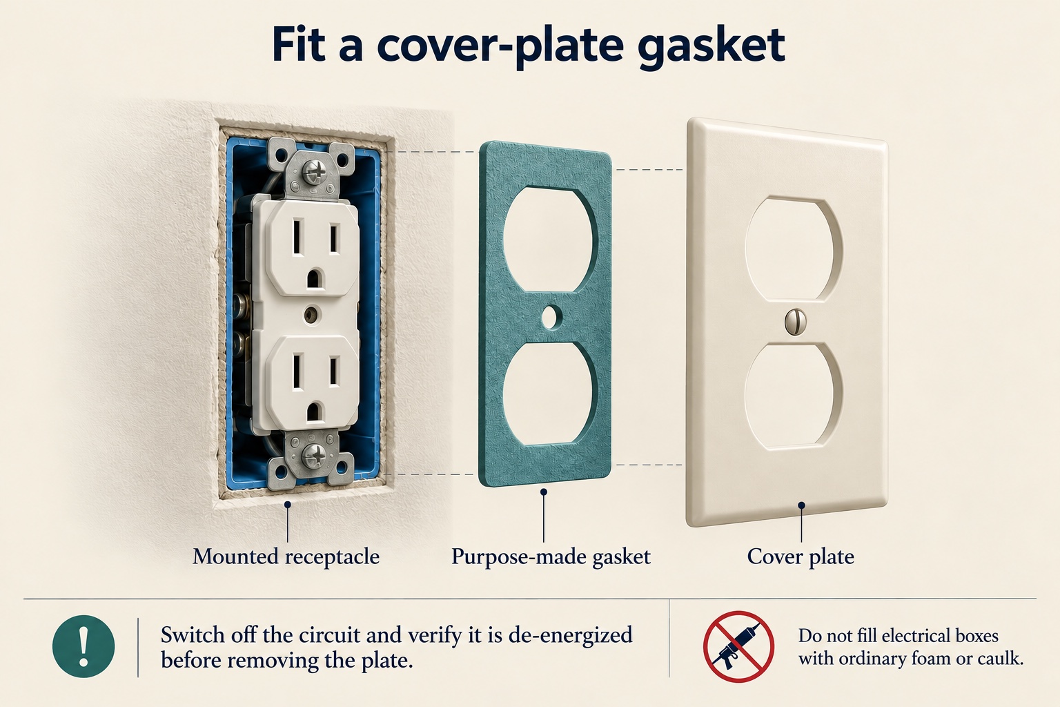
Choose a purpose-made gasket certified or listed for use behind electrical cover plates, with a CSA, UL/cUL, ETL/cETL or equivalent mark accepted by the local electrical authority. Turn off the circuit and verify that it is de-energized. Remove only the cover plate; fit the correct purpose-made gasket. Refit the plate as directed; check that the gasket seats evenly. Do not fill electrical boxes with ordinary caulk or foam. Wiring work: electrician.
Baseboards and window or door casing
- Check for a leaking stationary seam and sound, dry surfaces.
- Clean and prepare the joint; apply a compatible flexible sealant.
- Inspect for gaps after curing. Use the same principle at casing.
Look for leakage where trim meets the wall, floor or frame. Compatible flexible caulk can seal suitable stationary joints. When trim is already being removed, sealing the underlying wall-to-floor or frame connection can be more effective than covering the visible crack. Protect finishes and investigate dampness or decay first; keep moving joints and drainage openings clear.
Sources: [13]
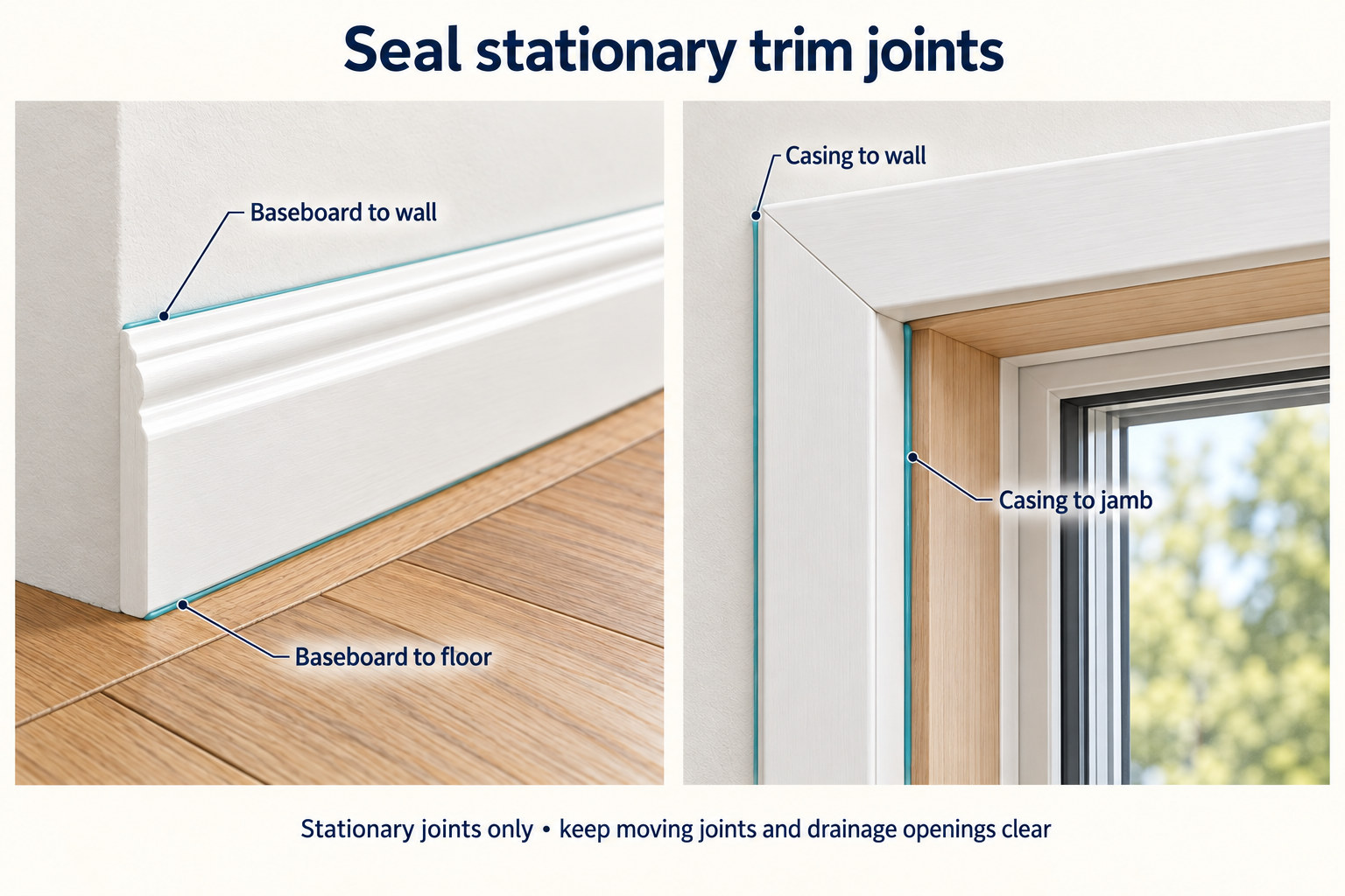
Check for a leaking stationary seam and sound, dry surfaces. Clean and prepare the joint; apply a compatible flexible sealant. Inspect for gaps after curing. Use the same principle at casing. Trim sealing may not close the hidden leak. Do not seal moving joints or drainage.
Starter project: replace a worn exterior-door seal
- Match the replacement strip to the existing door and joint.
- Prepare the surface and fit it continuously without stretching.
- Close and latch; check even contact and easy, safe operation.
Choose an ordinary exterior door you can reach from a stable floor. First check whether its frame is sound and the door closes and latches normally. If it sags, binds or has decay, address that problem first; thicker foam will not correct the geometry. Ask the responsible person about approved components before working on a fire-rated or shared-building door.
- Identify the existing seal profile and how it attaches. Choose a replacement suited to the door and exposure, using the door or seal manufacturer's directions.
- Measure each run and inspect the corners. Remove the failed strip only as directed, without disturbing damaged or suspect finishes.
- Clean and dry the receiving surfaces as required. Cut and fit the replacement according to its instructions; avoid stretching it to bridge a shortfall.
- Close and latch the door. Inspect contact around the perimeter. A strip of paper held in the closed joint can reveal uneven contact, but does not measure airtightness.
- Open and close the door several times. Adjust as the product permits; the seal must not prevent normal operation, latching or safe exit. Recheck it after use rather than assuming the first fit will last.
Sources: [8]
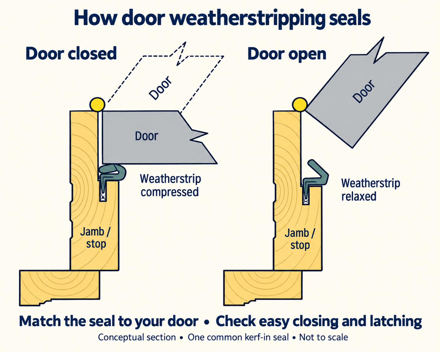
A flexible weatherstrip stays seated in the jamb kerf in both illustrated states. The closed door presses against its flexible profile. Match the replacement to the existing door and joint, follow product instructions, and check even contact and easy closing, latching and safe exit. Conceptual section showing one common seal type, not to scale.
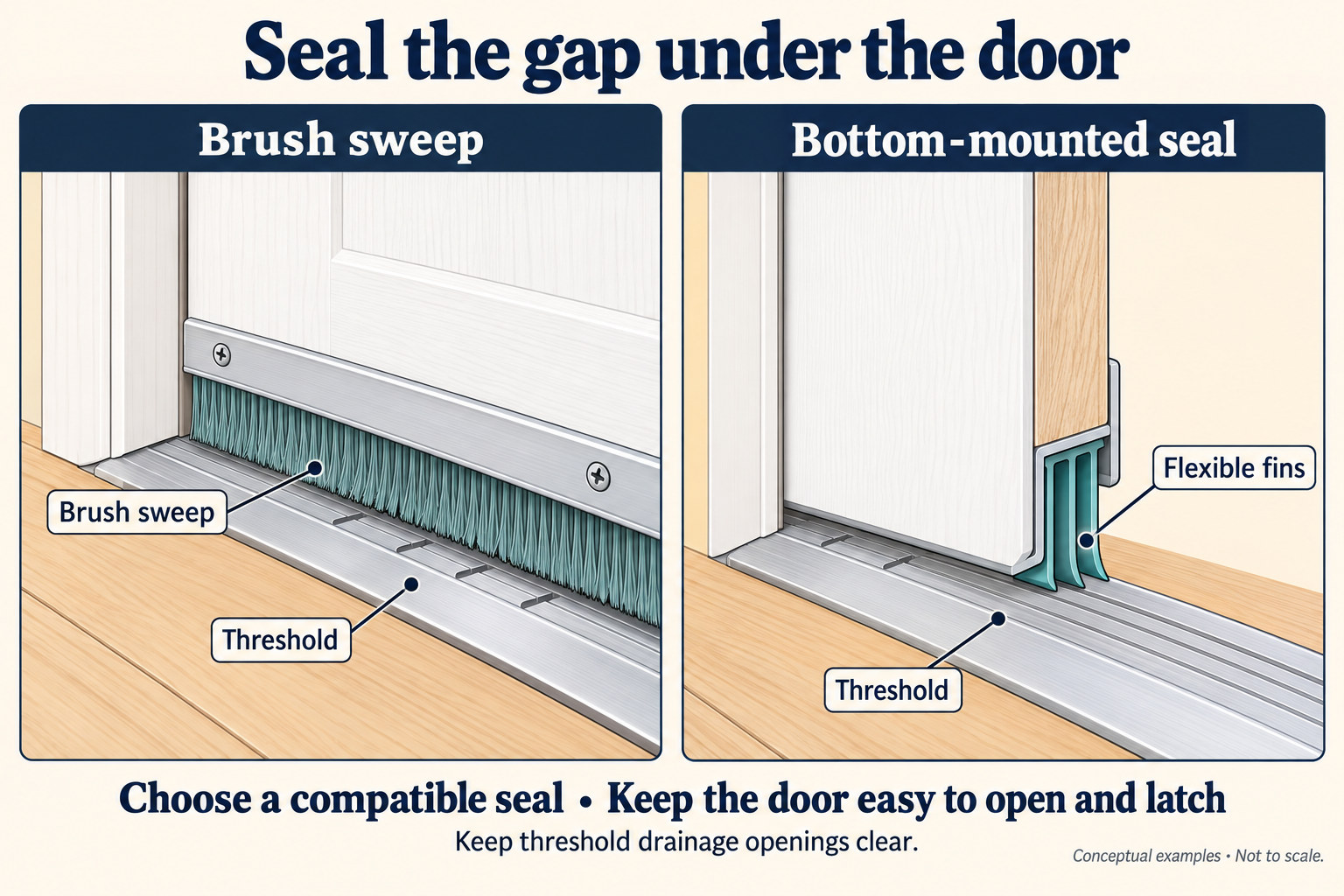
The brush sweep mounts on the door face; the alternative bottom-mounted shoe carries flexible fins beneath the door. Both illustrated seals contact the stationary threshold. Choose a compatible product and follow its instructions; keep the door easy to open and latch, preserve safe exit, and leave threshold drainage openings clear. Conceptual examples, not to scale.
Another small project—only when the attic hatch is safely accessible
Think of the hatch into a vented, unconditioned attic as an outside door above your head. That attic can approach outdoor temperatures in cold weather and become hotter than outdoors in sunshine. You would not choose a bare sheet of plywood as an insulated front door; a bare attic lid is not a complete thermal boundary either. It needs insulation and a dependable perimeter seal. Just as with door trim, the stationary frame and casing also need to be caulked or otherwise sealed to the ceiling air barrier—separately from the gasket around the moving lid. [12]
This is not an invitation to climb into an unknown attic. If the work cannot be done with safe access, or involves disturbed insulation, suspect vermiculite, moisture damage, wiring or unfamiliar construction, ask a qualified contractor. Never use ceiling drywall or insulation as a walking surface. Preserve roof ventilation and required access, clearances and fire protection; a vented-attic detail does not transfer automatically to an insulated roofline.
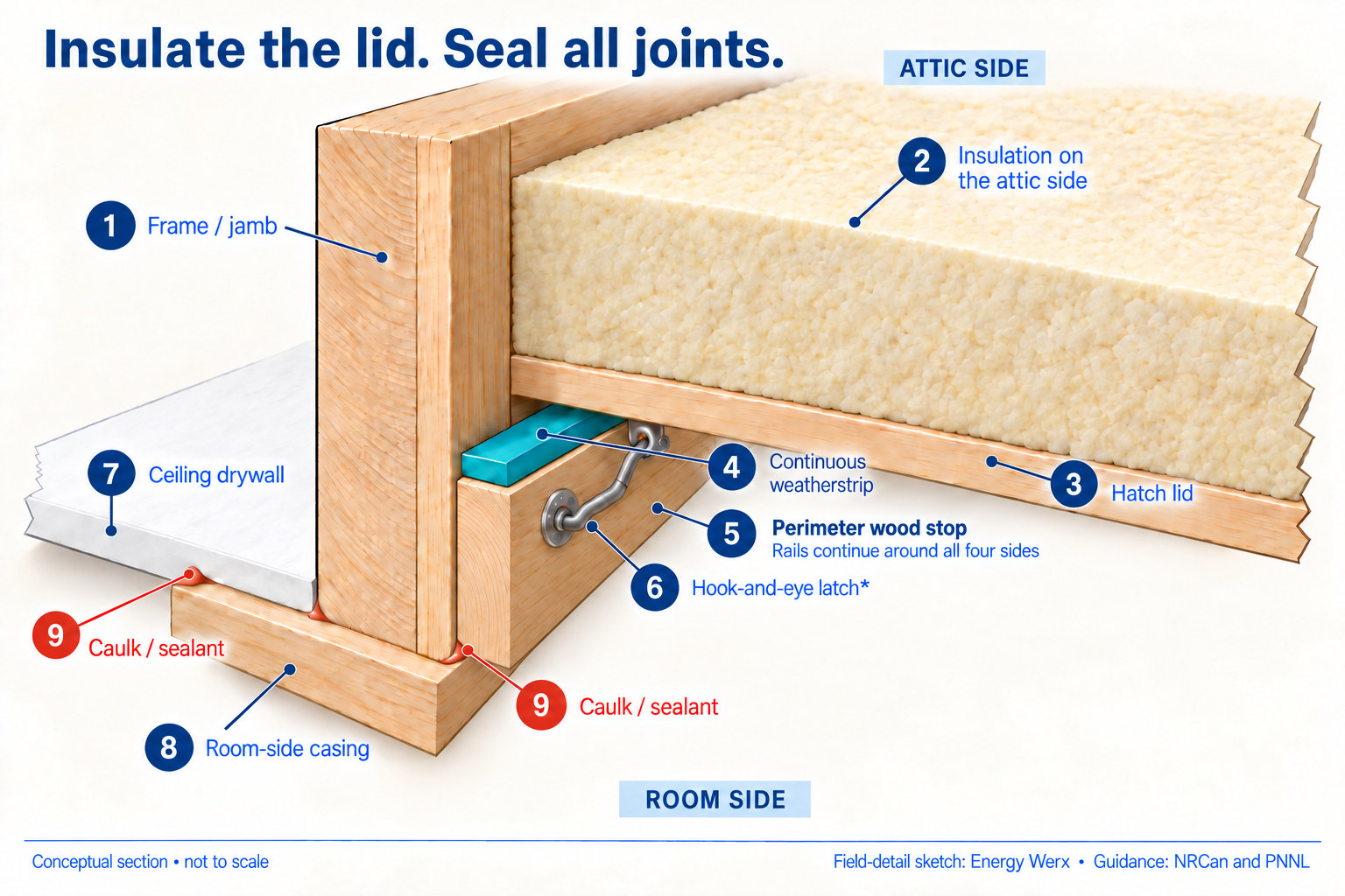
1. Frame / jamb: forms the sides of the hatch opening.
2. Insulation: sits on the attic side of the hatch lid to reduce heat flow.
3. Hatch lid: closes the opening and rests against the weatherstrip.
4. Continuous weatherstrip: sits between the wood stop and lid, continuing around all four sides.
5. Perimeter wood stop: rectangular rails fixed to the inside of the jamb support the lid and weatherstrip around the opening.
6. Hook-and-eye latch: connects the stop rail to the lid underside to help hold the lid against the seal; hardware shown is illustrative.
7. Ceiling drywall: meets the outside of the jamb at the ceiling opening.
8. Room-side casing: covers the ceiling edge, leaving a small reveal at the jamb.
9. Caulk / sealant: seals stationary casing-to-drywall and casing-to-jamb joints, shown in red.
Conceptual detail, not to scale. Rail size, insulation thickness, hardware and fasteners are illustrative rather than specifications. Retain safe access and required fire protection.
Agree on the work and the safety checks together
Qualified assessment should address combustion safety and contaminants before testing or sealing. Depressurization can draw pollutants from hidden spaces; suspected hazardous materials may require remediation or a different testing approach.
Ask the contractor to identify priority paths, suitable materials, access limitations and any work needed first. Heat-producing equipment, flues, electrical components and fire separations require appropriate details; a generic foam recommendation is not enough. Preserve intended ventilation, combustion-air and drainage functions. This article does not provide instructions for sealing those locations or blocking vents.
Check the result and keep a record
Photograph the locations before and after work, note materials used and keep a list of unresolved paths. Ask how ventilation and combustion safety will be checked. For measured before-and-after leakage, read Blower-door testing: what −50 Pa and ACH50 mean.
Questions worth taking with you
- Which gaps cross the air barrier rather than only the decorative finish?
- What materials and access are suitable for each location?
- Which locations need a qualified contractor or electrician?
Sources
- U.S. Department of Energy Consumer Guide to Air Sealing the Home
- Natural Resources Canada Keeping the Heat In — Section 3: Materials: insulation, house wrap barriers and weatherstripping
- Natural Resources Canada Keeping the Heat In — Section 4: Comprehensive air leakage control in your home
- U.S. Department of Energy / Pacific Northwest National Laboratory Building America Solution Center: Enclosure Leakage Test
- U.S. Department of Energy / Pacific Northwest National Laboratory Building America Solution Center: Whole-House Ventilation Strategies for New Homes
- DOE / PNNL Add Weatherstrip to Windows and Doors
- DOE / PNNL Home Air Sealing
- DOE / PNNL Air Seal and Insulate Attic Access
- U.S. EPA Protect Your Family from Asbestos-Contaminated Vermiculite Insulation
- Natural Resources Canada Keeping the Heat In (2012), section 4.2.5, attic hatch, printed page 48 / Figure 4-7
- Natural Resources Canada Keeping the Heat In (2012)
- Pacific Northwest National Laboratory Air Sealing Electrical Wiring
- Electrical Safety Authority Recognized Certification Marks for Electrical Products