

Energy IQ / Comfort IQ / Build IQ
Thermal bridging: the heat paths around insulation
Understand why studs, concrete and metal connections change a wall’s performance, and how exterior insulation and thermal breaks help.
Our articles are a starting point, not a professional assessment of your home.
DraftA work in progress, prepared by the HouseIQ.pro team.Editorial and professional review are not yet complete.
A thermal bridge does not need a hole
A thermal bridge is a part of an assembly where heat crosses more readily than through the surrounding insulated area. A solid wall stud can do this even when no air leaks past it. Heat travels from the warmer side toward the colder side: outward during heating weather and inward when the outside is warmer than an air-conditioned room.
Air leakage is another mechanism. It requires an opening or connected path and a pressure difference. A wall can have both problems, but closing an air leak does not change the conductivity of a stud. Equally, adding insulation does not automatically make every joint airtight. A useful proposal identifies the thermal-control work and the air-control work separately.
Look at repeated framing and one-off connections
Studs and plates form repeated paths through an otherwise insulated framed wall. Extra framing around openings or at corners changes the amount of wood in the assembly. Steel is highly conductive, so thin steel framing can influence heat flow well beyond what its small cross-sectional area might suggest. Simply filling the adjoining cavity does not remove that path.
Other bridges occur at junctions: a concrete floor reaching a balcony, a slab edge, a metal cladding support, or the connection between a wall and another assembly. A repeating pattern and a single substantial connection need different treatment. Ask the designer to identify both on the drawing instead of stopping the review at a typical patch in the middle of the wall.
Ask what the quoted R-value actually includes
Nominal R-value generally describes an insulation product. Effective assembly performance accounts for the other materials and their proportions. NRCan’s illustration places R-20 batts in a 2×6 wall and shows an effective result of about R-17. That example is a reminder to compare the finished assembly, not a rule for every R-20 wall.
A calculation for a repeating section may include studs but omit floor edges, corners or window connections. Ask what “whole wall” includes in the particular report. Windows and doors may be accounted for separately in a building calculation. Also keep units consistent: Canadian RSI is metric thermal resistance, while the R-values in this article use imperial units. Neither is a direct prediction of annual bills.
There is no universal 20–40% penalty
How much a bridge reduces performance depends on the material, its geometry, the insulation around it and what the comparison includes. Building Science Corporation describes substantially different effects for wood framing, steel framing and concrete-block webs. A single percentage cannot represent all three, let alone every connection in an existing home.
When a quote mentions a percentage loss, ask “compared with what?” An insulation label, a wall without framing, and a whole building are different baselines. A reduction in wall R-value is also different from the percentage increase in heat flow through that wall. These distinctions help expose an impressive-looking number that does not actually answer your question about the proposed work.
An invented example shows why weak paths matter
Imagine a simplified layer with two independent, straight heat-flow paths. Invented assumptions: 80% of its area has R-20 resistance and 20% has R-6. Both paths experience the same temperature difference. There are no openings, shared surface layers, moisture effects or sideways heat spreading. This is an explanation of the arithmetic, not a model of a real wall.
Heat flow follows conductance, the reciprocal of resistance. Add the area-weighted conductances: 0.80 ÷ 20 + 0.20 ÷ 6 = 0.0733. Taking the reciprocal gives an equivalent R-value of about 13.6. Averaging the two R-values directly would miss how strongly the easier path contributes.
Now, still assuming two completely independent paths with no sideways heat spreading, give each path an additional R-5. Their resistances become R-25 and R-11; 1 ÷ (0.80 ÷ 25 + 0.20 ÷ 11) is about R-19.9. It remains below an entirely R-25 layer. This comparison is deliberately simplified: it is not a whole-wall design calculation or an estimate of a real exterior-insulation retrofit. Real assemblies need the appropriate calculation method or multidimensional analysis.
| Assumed path | Before | With added R-5 |
|---|---|---|
| 80% of area | R-20 | R-25 |
| 20% of area | R-6 | R-11 |
| Equivalent simplified layer | R-13.6 | R-19.9 |
Continuous insulation covers more than the cavities
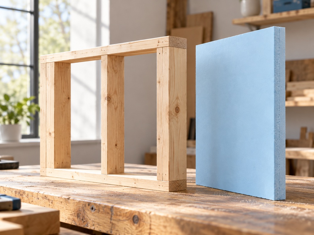
Continuous exterior insulation places a thermal layer across the outer face of framing rather than only between its members. That adds resistance in front of the studs as well as the insulated cavities. It is especially useful to consider when the siding is already due for replacement, because the wall’s exterior layers are part of the project.
Continuous does not mean that all penetrations disappear. Ask how the insulation connects at openings, the roof edge and the foundation. Also identify the actual product and thickness; rigid foam and mineral-fibre boards have different properties. The drawing should show thermal coverage alongside water management and the cladding support system. A product name alone cannot establish continuity.
Sources: [5]
Attachments can remain bridges through the new layer
Cladding still has to be supported. Metal screws, brackets or rails passing through insulation can provide remaining heat paths. Their effect depends on their material, size, number and arrangement. A broad metal support crossing the layer and an isolated fastener are not thermally equivalent; neither should be declared harmless solely because exterior insulation is present.
COMSOL’s published demonstration of an iron bar crossing insulation illustrates why point connections are a three-dimensional heat-flow problem. It is not a test result for a particular siding screw. For your project, request performance information for the proposed attachment layout. Structural capacity, corrosion resistance and thermal performance have to be resolved together; removing or substituting fasteners is not a homeowner remedy.
Concrete connections need structural thinking too
A concrete element that continues across the insulated boundary can carry heat around the insulation. Balcony slabs are a clear example. Concrete-block webs likewise remain conductive routes even when the hollow cores receive insulation. Filling the open spaces does not turn the solid connections into insulation.
A thermal break introduces a less-conductive part into a connection, or changes the arrangement so insulation can continue past more of it. A structural thermal-break system still has to transfer the required forces. Some heat paths may remain through its connectors. Ask for the design’s resulting performance, not a promise that the word “break” means zero heat flow. Existing balconies and load-bearing connections require specialist assessment, not improvised separation.
The coldest spot can matter before the energy total
A bridge can create a colder interior surface during winter. That may affect comfort or become a condensation location if the surface temperature reaches the indoor air’s dew point. Whether this happens depends on both the surface temperature and indoor moisture conditions. A low average wall heat loss does not guarantee that every small detail stays warm enough.
Ask an assessor to consider the local surface temperature as well as total heat transfer. Repeated dampness near a junction deserves investigation because a water leak, air leak and thermal bridge can produce overlapping symptoms. In a cooled Florida home, the seasonal temperature and moisture relationships differ from a Canadian winter. The cause should be established before assuming that a winter-style insulation fix answers the problem.
Changing insulation also changes the moisture plan
Exterior insulation can keep the underlying sheathing warmer during heating conditions, but material choice and thickness affect the result. The wall still needs rain control and a drying strategy appropriate to its climate and existing layers. Insulation and moisture planning belong in the same design conversation.
Ask which layer controls liquid water, which limits air leakage and how the wall can dry after incidental wetting. A thermal improvement should not quietly remove a drainage route or create an unassessed drying restriction. Building Science Corporation’s Guide to Insulating Sheathing treats structural sheathing, the drainage plane and climate together. That is a useful standard for reviewing a proposal, without copying a generic wall detail into your own house.
Sources: [9]
Turn the explanation into a better proposal
For a complex connection, a professional may use two- or three-dimensional heat-flow modelling. Berkeley Lab’s THERM documentation explains that geometry, material properties and boundary conditions must be defined before calculating U-factors and local temperatures. A colourful result is only as relevant as those inputs. Ask whether the model represents the detail that will actually be built.
Bring a short list of comfort concerns and upcoming work to the assessment. Then ask which connections deserve attention now, which can be improved when cladding or windows are replaced, and which would require disproportionate structural work. Keep the proposed details and calculation scope with the quote. The aim is a measurable improvement in the right places, with clear limits, rather than an unsupported claim that every bridge has vanished.
Questions worth taking with you
- Does the quoted thermal value describe the insulation, a repeating wall section or a whole assembly with junctions?
- What baseline and calculation support any percentage-loss or savings claim?
- How will the exterior insulation connect at openings, floors, roof edges and foundations?
- What thermal effect remains from the proposed fasteners and supports?
- Have local surface temperatures, seasonal moisture and structural requirements been considered together?
Sources
- Building Science Corporation / John Straube BSD-011: Thermal Control in Buildings
- Building Science Corporation / John Straube BSD-014: Air Flow Control in Buildings
- Natural Resources Canada Keeping the Heat In — Section 2: How your house works
- U.S. Department of Energy / Pacific Northwest National Laboratory Advanced Framing: Minimum Wall Studs
- U.S. Department of Energy / Pacific Northwest National Laboratory Continuous Rigid Insulation Sheathing
- Building Science Corporation / Joseph Lstiburek BSI-005: A Bridge Too Far
- COMSOL Thermal Bridges in Building Construction — 3D Iron Bar Through Insulation Layer
- Lawrence Berkeley National Laboratory THERM Software Downloads — About THERM
- Building Science Corporation Guide to Insulating Sheathing